Citroen Relay Fuse Box Diagram 2008
Fuses and relay Citroen C-Crosser
For the Citroen C-Crosser 2007, 2008, 2009, 2010, 2011, 2012 model year.
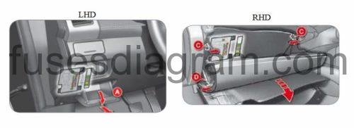
Fuse box in passenger compartment.
fuse box location.
fuse box diagram.
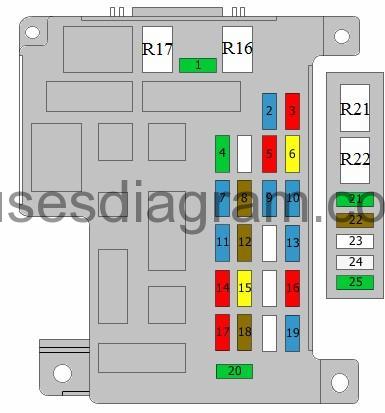
legend.
| Fuse | Amps | Circuits protected |
|---|---|---|
| 1 | 30A | Blower motor |
| 2 | 15A | Brake pedal switch |
| 3 | 10A | Rear fog light |
| 4 | 30A | Windscreen wiper motor Washer pump |
| 5 | 10A | Diagnostic connector |
| 6 | 20A | Rear door locking Front door lock actuators Boot lock Electric mirrors |
| 7 | 15A | Audio system Multifunction switch Handsfree control unit Multimedia display |
| 8 | 7,5A | Fuel additive control unit Multifunction switch Control panel Air-conditioning control unit Transponder control unit Ignition switch |
| 9 | 15A | Control panel Multifunction switch |
| 10 | 15A | Light signal Right headlight Trailer connector socket Right tail light Left headlight Left tail light |
| 11 | 15A | Rear wiper motor |
| 12 | 7,5A | Control panel Multifunction switch Headlight levelling control unit Differential control unit Additional heater relay 1 Additional heater relay 2 Additional heater relay 3 ABS control unit Transponder control unit Heater panel Air-conditioning control unit Parking switch Parking assistance control unit Load angle sensor(s) Relay, heated seats Rear demister Airbags and pretensioners unit |
| 13 | 15A | Front 12V socket |
| 14 | 10A | Ignition switch |
| 15 | 20A | Sunroof motor |
| 16 | 10A | Rear-view mirror Audio system |
| 17 | 10A | Differential control unit |
| 18 | 7,5A | Airbags and pretensioners unit Reversing light switch Trailer connector socket |
| 19 | 15A | Rear accessory socket Rear 12V socket |
| 20 | 30A | Power window control Driver's door lock Passenger's power window switch Switch, rear right power window(s) Switch, rear left power window(s) |
| 21 | 30A | Relay, rear demister |
| 22 | 7,5A | Relay, front demister Relay, rear demister Rear demister Front mirrors |
| 23 | not used | |
| 24 | 25A | Electric rear seats |
| 25 | 30A | Relay, heated seats |
| R1 | no location information | Fuel pump relay |
| R2 | no location information | Windscreen wiper(s) relay |
| R3 | no location information | Windscreen wiper main relay |
| R4 | no location information | Windscreen washer |
| R5 | no location information | Rear windscreen washer |
| R6 | no location information | Tailgate lock relay |
| R7 | no location information | Rear wiper relay |
| R8 | no location information | Rear fog light relay |
| R9 | no location information | Door unlock relay |
| R10 | no location information | Door lock relay |
| R11 | Not used | |
| R12 | no location information | Power window relay |
| R13 | no location information | Folding mirror |
| R14 | no location information | Folding mirror |
| R15 | no location information | Accessory socket relay |
| R16 | Blower relay | |
| R17 | Central locking relay | |
| R18 | no location information | Ignition relay |
| R19 | no location information | Accessory relay 2 |
| R20 | no location information | Accessory relay 3 |
| R21 | Relay, heated seats | |
| R22 | Relay, rear demister |
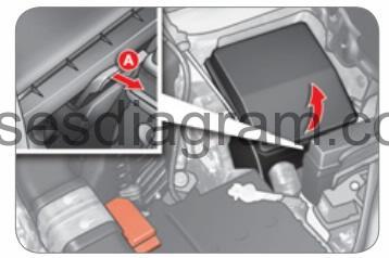
Fuse box in engine compartment.
fuse box location.
The fuse box is placed near the battery (left-hand side).
fuse box layout.
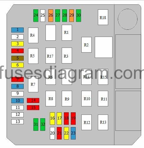
legend.
| Fuse | Amps | Circuits protected |
|---|---|---|
| 1 | 15A | Front fog light relay |
| 2 | 7A | Engine control unit |
| 3 | 20A | Automatic transmission |
| 4 | 10A | Horn relay |
| 5 | 7,5A | Alternator |
| 6 | 20A | Headlight washer timer relay |
| 7 | 10A | Air-conditioning compressor relay |
| 8 | 15A | Engine control unit |
| 9 | Not used | |
| 10 | 15A | Relay, front demister |
| 11 | Not used | |
| 12 | Not used | |
| 13 | Not used | |
| 14 | 10A | Left headlight |
| 15 | 10A | Right headlight |
| 16 | 20A | Left headlight |
| 17 | 20A | Right headlight |
| 18 | 10A | Left headlight Headlight range control Headlight levelling Headlight levelling control unit |
| 19 | 10A | Right headlight |
| 20 | Not used | |
| 21 | 10A | Ignition coil |
| 22 | 20A | Engine management relay Engine control unit Electronic throttle control motor relay Mass airflow meter Oxygen sensor Canister purge solenoid Vehicle speed sensor Variable valve timing Electronic EGR valve |
| 23 | 15A | Feed to built-in systems interface |
| 24 | 30A | Start inhibitor relay |
| 25 | Not used | |
| 26 | 40A | ABS control unit ESP control unit |
| 27 | 30A | ABS control unit ESP control unit |
| 28 | 30A | Cooling fan relay, left side Cooling fan relay, right side |
| 29 | 40A | Cooling fan relay, right side |
| 30 | 30A | Feed to built-in systems interface |
| 31 | 30A | Radio/amplifier |
| 32 | Not used | |
| R1 | Throttle control motor relay | |
| R2 | Additional heater relay 1 | |
| R3 | Relay, front demister | |
| R4 | Front fog light relay | |
| R5 | Horn relay | |
| R6 | Headlight washer timer relay | |
| R7 | Air-conditioning compressor relay | |
| R8 | Main beam relay | |
| R9 | Power cut-off relay | |
| R10 | Start inhibitor relay | |
| R11 | Additional heater relay 2 | |
| R12 | Main beam relay | |
| R13 | Engine management relay | |
| R14 | Fan relay | |
| R15 | Cooling fan relay, left side Cooling fan relay, right side | |
| R17 | Gear lever blocking control relay | |
| R18 | Cooling fan, low-speed relay |
Additional fuse box in engine compartment.
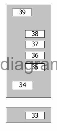
| Fuse | Amps | Circuits protected |
|---|---|---|
| 33 | 80A | Feed to built-in systems interface Fuse and relay box in passenger compartment |
| 34 | 120A | Fuse and relay box in engine compartment Or Fuse and relay box in engine compartment Connector |
| 35 | 40A | Additional heater relay 2 |
| 36 | 60A | Additional heater relay 1 Pre-post heating |
| 37 | 30A | Additional heater relay 3 |
| 38 | 80A | Feed to built-in systems interface Fuse and relay box in passenger compartment Or Feed to built-in systems interface Fuse and relay box in passenger compartment Headlight relay Rear fog light |
| 39 | 175A | Alternator (120A also used) |
Posted by: lisaagationoaz.blogspot.com
Source: https://fusesdiagram.com/citroen/fuses-and-relay-citroen-c-crosser.html

Posting Komentar untuk "Citroen Relay Fuse Box Diagram 2008"